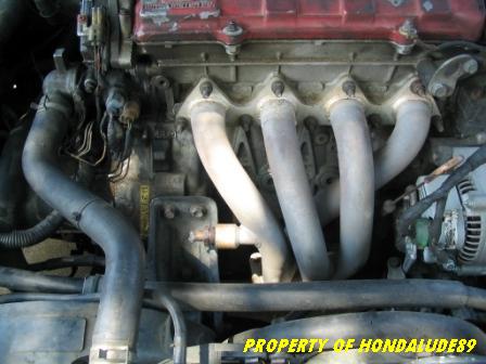
Oh yeah, if you still have the stock header or an aftermarket one with the two bungs on top, get those plugged or leave the two sensors there. Also note that you will need a new O2 sensor bung drilled and welded at the collector under the car.
Materials:
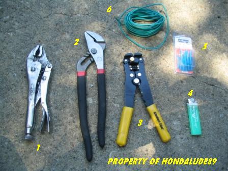
1)Vise Grips
2)Channel Locks
3)Wire Strippers/Clamper/Cutters
4)Lighter or torch
5)Heat Shrink Wire Connector (crimp style)
6)Wire
You will also need a four wire O2 sensor. Any 4-wire O2 sensor will work. I got mine off a 1993 Acura Integra (Bosch). I took the sensor and the plug. I took the plug so that in the end it will look like stock and not "modded"
Take into account that I was too cheap to go rent the O2 sensor socket from Vatozone so I used the Vise Grips to remove the sensors. I also listed the Channel locks in case you don't have access to a set of Vise Grips. I recommend the Vises instead of the Channel locks. Make do with what you have.
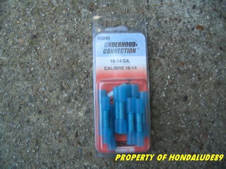
Here are the wire connectors that I used:
Ok, here we go. Jack the front of the car up and support it on jack stands and block the rear wheels. Open the hood and remove the negative (black) cable from the battery.
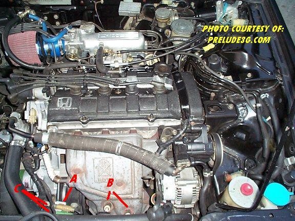
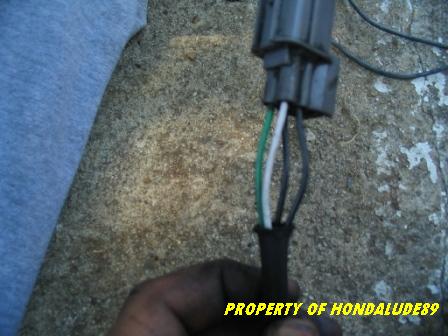
A)Unplug the two O2 sensors from their connectors.
B)Get your Vise Grips or Channel Locks and remove the O2 sensors. Leave them on there if you have the stocker or the 88-89 aftermarket header. Before you do this, make sure to remove the heat shield so you can get to the sensors.
C)Get your wire cutters and cut the wires from the plug connectors
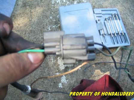
This is what it looks like after cutting the connectors and stripping a bit of insulation from the wires.
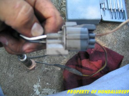
Next get your O2 sensor and connector plugs if you got the whole thing from a donor car.

Next look at the O2 sensor and you should have the four wires colored: Black, Black, White and Green. The colors vary. For this O2 sensor the colors represented different functions.
Green - Ground *** Black - Ground *** White - Signal *** Black - Switched 12V
Take into account that it does not matter what black wire you use for the 12V or ground. I tested both blacks to power and they both heated the sensor.
Here we have the 12V power source wire (black) and the signal wire (white).
Here we have both grounds(black & green).
Next take you wire strippers and strip insulation from all four wires. Take some of the wire you have and cut the desired length of wire for each of the wires.
Take your heat shrink crimp type connectors and join the sensor connectors and the additional wire.
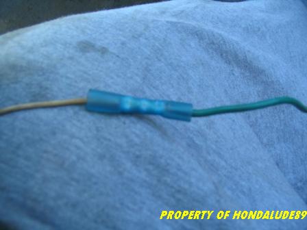
You should have something like this after you crimped the wires together.
Next take you lighter or torch and apply heat to the crimp connectors.
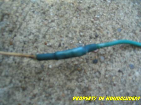
This is what it will look like when done.
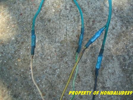
This is what it should look like when all connections at the O2 sensor are crimpped and heated. This is weather proof and are pretty strong thanks to the crimping and heat shrink.
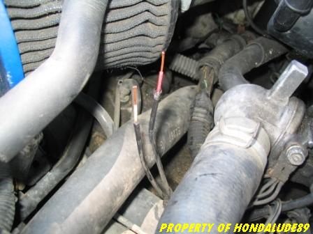
Take you harness or O2 sensor and walk to the engine. Find a way to route your wires from under the car to the top into the engine bay. Take your signal wire and route it to your two original O2 signal wires. Take the original two wires and twist them together. Get a crimp connector and connect the signal wires together.
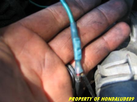
This is what the finished product looks like. This is after crimping the wires together and applying heat.
Next take your two ground wires and find a suitable body ground.
I connected a ground wire to an existing ground wire on the firewall.
I connected the other ground wire to the firewall. The bolt happened to hold my alarm siren to the firewall.
I don't see why you couldn't bolt both ground wires to the same place. I just chose to do it this way.
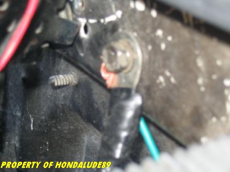
This is after all ground wires have been bolted down.
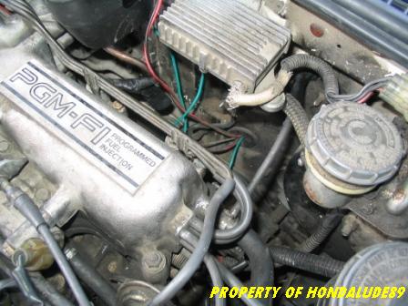
I took my final wire, the power wire, and routed it to the inside of the cabin. I routed it through an existing hole/grommet on the firewall.
Finally find a 12V switched source. It has to be a wire which shows 12V when the car is on.
My camera decided to take a break and run out of battery so I didn't get any pics.
I decided to remove the steering column cover and find the ignition switch harness. I connected the power wire to the White/Red wire on the ignition switch plug. I just unplugged the connector and removed a bit of insulation from the White/Red wire and plugged my power wire into it. I then insulated the connection with electrical tape and plugged the harness back in.
Re-assemble the steering column and check all your connections/connectors.
Get back under the car and bolt in your O2 sensor in the bung.
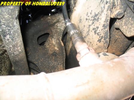
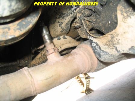
This is after it's all bolted in.
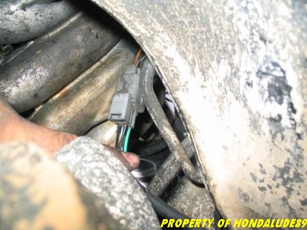
This is what my setup looked like after I bolted the O2 sensor and plugged it back into the harness connector. Now this doesn't apply if you just had the O2 sensor without the harness plug.
Now is the moment of truth. Connect the negative wire back to your battery. Get inside the car and start it. Everything should be fine, no CELs.
Let the car warm up to normal temperature and bleep the throttle, it should be more responsive. If everything is fine lower the car and put your tools away and take it for a spin.
That should be it.
Have fun!
Take into account that you can solder the wire connections and use shrink tubing, but I decided to use the easiest stuff for people who are not mechanically inclined.
-Carlos